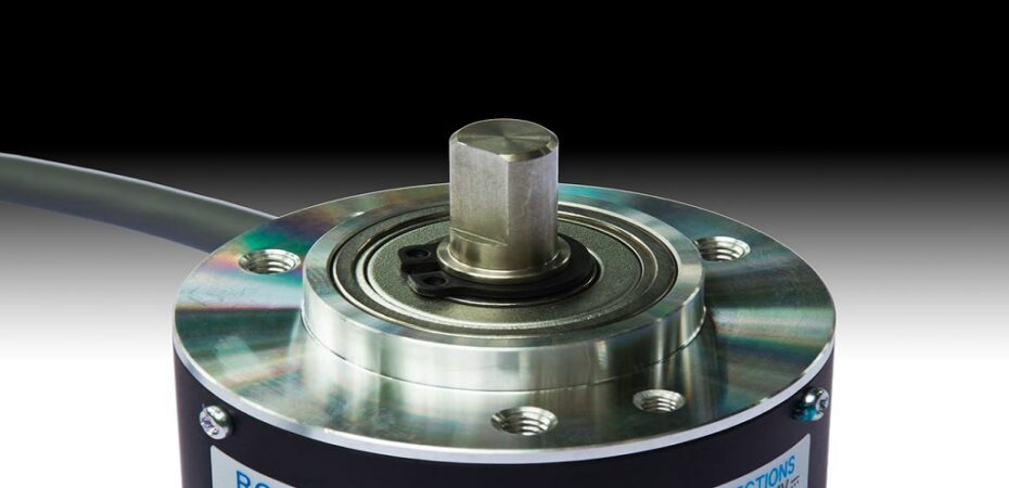
An optical rotary encoder is an optical position sensor that uses a rotating beam of light to measure the angular velocity (rotational speed) and the distance traveled by the rotating object. It can be used to provide feedback on a machine tool during machining so that the operator knows when to stop, for example.
An optical rotary encoder consists of four parts: an input stage, a photocell, an output stage, and a trimmer. The trimmer is adjusted carefully so that as the rotor/bearing turns from one extreme position to another, it maintains constant angular velocity as measured by the photocell.
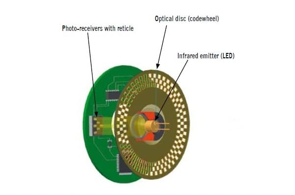
The input stage of an optical encoder uses a light emitting diode (LED) and a photodetector that are arranged, so the light beam is at 90 degrees to the axis of rotation. The light beam is emitted by the LED, reflected off the rotating part, and returned to a photodetector via a lens. A circuit inside the optical encoder then measures at what point in its rotation the beam is blocked by the incoming signal from a photodetector and produces an output signal.
Optical Rotary Encoder Basics
A light-emitting diode (LED) is a semiconductor light emitter that emits light in a narrow spectrum of the visible spectrum.
It is connected to a photodiode through a lens and an electronic circuit for detecting the photocurrent produced by the interaction of light with the silicon detector. The output of this circuit is called an optical signal or optical indicator, which indicates the angular velocity and distance traveled by the object rotating at its shaft.
An optical encoder works by using external forces that are applied to it to monitor various process parameters. In full-scale applications, any mechanical force can be used because this will not affect its precision performance over time.
The optical encoder is designed in such a way that it can be integrated into the rotating system. It has two major functions, one is to measure the turning angle of the machine when it reaches the extreme limit and the second is to determine the position of the shaft.
Working Principle of Optical Encoder
An optical encoder is designed with an LED, which emits light that shines on a disc surface from one side of the optical system lens, making a beam toward the detector. When the beam reaches the sensor, it is reflected back and again shines on the disc surface from another side of the optical lens. This time one side is shining on both ends of the disc surface, making a beam across the detector from both ends. When the beam reaches the detector, it is reflected back but not at 90 degrees toward LED as before.
When the disc rotates further toward LED, there is an angle between two beams, so this point has zero light output. At this point, the rotation has reversed like an ‘S’ shape. Consider that when the disc rotates further towards LED, then there will be a gap between two beams, and so this point has maximum light output. At this point, the rotation has reversed like an ‘S’ shape, as above.
The encoder will provide a signal proportional to the shaft angle, which is proportional to the distance traveled. Therefore the output signal of an encoder is a function of time and can be used to determine the instantaneous position of the rotating part and, thus, control the machine.
The above figure shows a basic connection diagram of the optical encoder.
Applications of Optical Encoders
The common applications for Optical Encoders are:
1. Measurement systems
Where the encoder is used to convert mechanical motion into an electrical signal that can be transmitted to a remote location (for example, in the monitoring of conveyor belt position on a moving assembly line).
Optical encoders are particularly suited for this type of application because they are compact, require no power source, and have no moving parts.
2. Machine tools
Where the encoder is used to signal the position of a rotating part.
3. Position measurement
where the encoder signals the position of a rotating part. In this application, position measurement accuracy is important, and this can only be achieved by measuring the shaft velocity. Optical encoders are particularly suitable for this type of application because they do not require power, and they operate within a narrow range in terms of shaft velocity.
4. Abandonment
where the encoder is used to measure the position of a rotating part, but cannot be powered in order to monitor the position of a rotating part without having to power it.
5. Machine calibration
where the encoder is calibrated at regular intervals using an external measurement instrument. The encoder can then be removed and replaced if it is not required for future use.
The process of setting an optical encoder is called set up. The set up includes setting the optical encoder and checking all the parts before supply to customers to be completely in contact with customer requirements.
When you mount an optical encoder onto a machine, you must first confirm its functional performance with the tools or machinery manufacturer. It will help you with the technical requirements for its engineering and calibration, and measuring data.
To do so, the tool or machinery manufacturer provides you with the technical requirements of the encoder. It is important to check it with your engineers to ensure they are consistent.
You must know how to use and adjust it. Otherwise, you might carry out errors in setting up. Also, check the operating instructions in order to know how to operate the encoder and where it has been placed on a machine tool or machinery. It should be adjusted properly with all its parts before supply to customers.
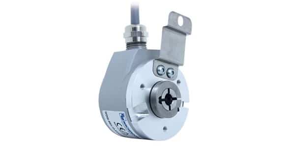
There are some variations of optical encoders:
The most widely used type of encoders uses LEDs for illumination and photovoltaic cells for detection. Single-sided photodiodes are fixed to the end of the rotating part and are used in particular for machine tools. The LEDs and photodiode are generally directed to one side at right angles to the axis of rotation. A complete model is shown above.
These encoders use LEDs only, so they do not require a photodiode. This has several advantages:
The circuit is simpler, and the units offer better resistance to dust and dirt. The main disadvantage is that with this type of system, it can be difficult to detect any vibration or lateral forces on the shaft, so you should use them only in applications where there will be no risk of these forces being applied.
Read also:

